





Scope and Low-Voltage Roles
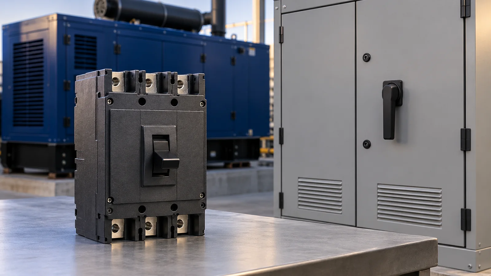
Plants run standby generators during power outages. These units serve as backup power sources for critical loads. Project engineers select generator circuit breakers for each set. A proper unit helps protect windings and cables during faults.
System needs change with machine size. This guide focuses on an industrial generator rather than portable generators. Power stations face different duties. Large plants use Eaton medium-voltage breakers built for large scale continuous current, high faults, and grid voltage.
Many data centers and industrial applications rely on commercial generators. This guide covers low-voltage setups only. For these sites, low-voltage power generation reviews compare available fault current with breaker trip curves.
Load Ratings Versus Fault Current
Teams must separate steady load ratings from fault ratings. A continuous current rating applies under stated running conditions. It differs from real power outputs for a prime power generator or standby unit.
Kilowatts alone do not define load current. Full-load amps depend on system voltage, phase count, and power factor.
Fault current also acts differently from load current. Unlike utility feeds, circuit breakers at the machine face current that drops over time. The Cummins application manual explains how field excitation controls govern sustained fault output.
Staff must check each supplied generator circuit breaker switch. Some sets include a non-automatic disconnect with no trip units. Rated load current does not establish a fault interruption rating or automatic fault protection.
A switch handle does not prove safe electrical isolation. Site rules demand approved lockout steps. Selecting protective circuit breakers for generators requires confirming automatic fault tripping.
Reading Fault Curves
A generator set has unique fault traits. Available current changes over time. Stored magnetic energy decays first. Then, field excitation supports sustained current.
Decay rates depend on the fault type and machine model. The STAMFORD guide provides model decrement curves. The maker can also provide model thermal-damage curves on request.
Staff compare breaker clearing times with factory curves. The breaker must open before fault heat exceeds winding limits. This check also accounts for planned load steps. Designers review the genset curves and site layout together to assess protection.
Checking the Site Design
Plant networks link several switching units. When an automatic transfer switch connects the alternate power source, staff check its withstand ratings against upstream clearing times.
Monitoring gear differs from fault clearing hardware. Modern generator control panels track engine data and alarms. Some models can send trip signals if wired for that task. Even so, physical circuit breakers must open to cut fault current.
Site studies set trip timing across the system. Where the approved design allows, the goal is to clear a faulted branch without tripping upstream feeds. Teams set trip delays to protect gear and support power flow.
Requesting Model Data
Buyers should review equipment data sheets rather than sales claims. Brochures often call an assembly high quality. Yet project sign-off requires verified test curves and device ratings.
During submittal checks, identify the circuit breaker, generator reactances, and excitation data for the specified industrial genset. Factors like fuel types, cooling system capacity, and fuel efficiency shape long term operating costs. Yet these engine traits do not set breaker trip curves or clearing times.
Alternator reactances provide machine impedance data. Decrement curves show fault current over time. Both inputs support fault studies.
Engineers also review cables, grounding, and operating modes. Qualified staff run coordination studies to assess device clearing against specified equipment limits.