


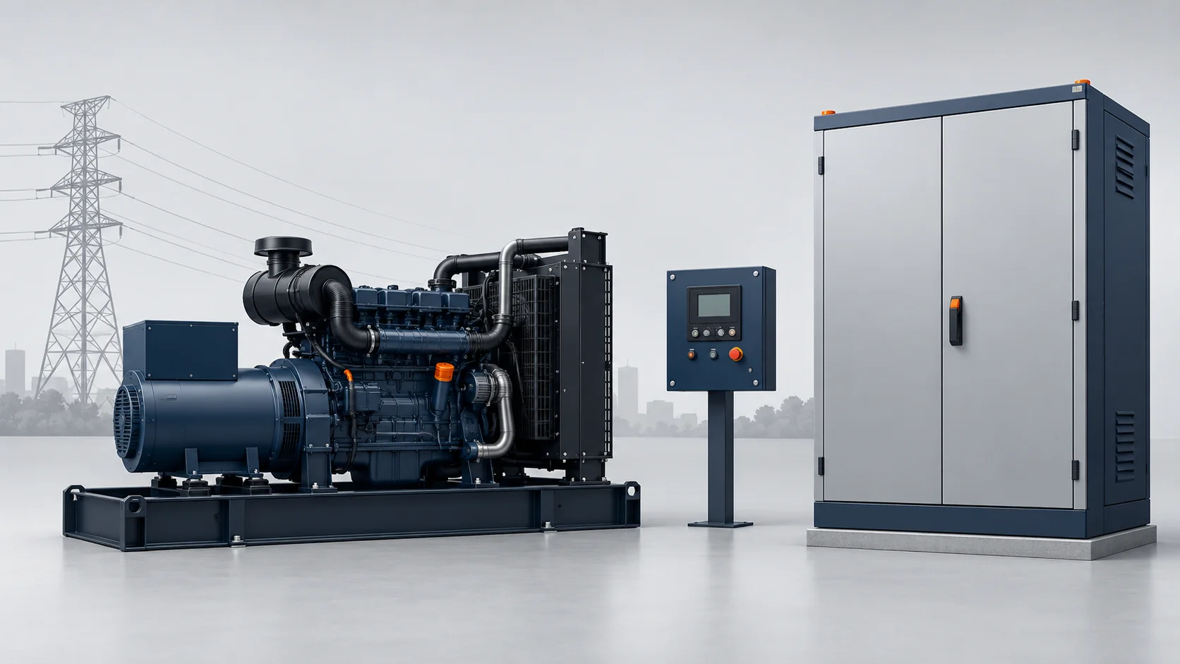



An automatic transfer switch (ATS) connects electrical loads to a primary power source. During a power failure, it shifts those loads to a configured backup power source. An ATS is distinct from a full transfer panel. Package contents vary by project, so teams must verify them.
In a typical setup, a transfer panel pairs with a standby generator for power outages. Project-assigned sensing tracks voltage and frequency on the utility lines. When the main source fails, a control signal starts the generator set if it is not already running.
In an open transition sequence, the switch disconnects the utility lines before connecting the backup generator. The switch transfers the load once the genset meets model voltage and frequency limits. When utility sources return, the switch transfers electrical power back per documented model and project logic.
Control and Main Power Switching
Plant designs separate control signals from main power switching. Engine generator sets use an engine controller to monitor the engine and alternator. The controller monitors machine alarms. It triggers a protective shutdown during configured faults.
The controller monitors power generation status and signals. The switching mechanism in the transfer panel carries the main load between specified sources. This mechanism feeds electrical loads per the site design. Staff must check the operating limits of each unit in the factory manuals.
Control logic varies by unit. Not every generator detects grid loss on its own. Engineers must check model manuals for matching interfaces and built-in transfer logic. Staff must log all ratings and signal interfaces for both the genset and transfer switch in project files.
Source Ratings and Load Data
Integrating a generator set starts with power system ratings. Engineers first check source voltage and frequency. They also confirm single phase versus three phase power. Generator set kW and kVA electrical ratings match the backup power source to site demand.
Teams check transfer switch ratings, including current, separately against utility sources.
Each generator data sheet applies only to its exact model and market. For instance, the Cummins C20D5P in the X1.3 line for India lists a 0.8 power factor. That figure is model-specific, not a general rule for Mexico or the US. In Mexico, project teams must check nameplate ratings on the chosen equipment for each site.
Engineers must also check motor inrush and starting load fit for the standby generator. Teams running diesel units can consult the SEER POWER guide on diesel generator fuel consumption. That guide examines generator fuel use. The article does not provide a transfer switch diagnostic procedure.
Transition Types and Brief Power Breaks
An ATS alone does not guarantee continuous power or prevent brief breaks. In Mexico, Schneider Electric catalogs the ASCO 7000 Bypass transfer switch line. The listing includes open, closed, and delayed transition options for specific models.
These options do not apply to every ASCO 7000 version. Teams must verify the exact offered version and local project requirements.
In an open transition design, the switch disconnects one source before it connects the next. During sudden utility power outages, a stopped generator must start before it supplies backup power. An already-running backup unit does not need an engine restart before transfer.
A closed transition switch can briefly parallel two live sources where permitted. Even so, a closed transition label alone does not guarantee unbroken power during an unexpected grid loss.
Critical facilities such as data centers often support sensitive loads, but not every load requires unbroken power. A qualified team must assess each load for the break duration it can tolerate. Projects needing continuous power must state that requirement alongside equipment ratings. Teams should add suitable bridging supplies or auxiliary systems only where needed.
Start Signals and Fuel Systems
Source control requires clear signal logic. The project design must define which device senses lost utility lines. It must state which unit sends the engine start signal. The design also determines which device grants permission to transfer.
Technical manuals confirm which signals the generator set accepts. They also specify how the transfer panel responds.
A transfer switch routes electrical power, not engine fluids or fuel flow. Industrial power generation uses both diesel engines and natural gas units. Buyers comparing these options must check factory fuel supply rules for the chosen model. Teams must also review site pipe work and fuel storage needs where they apply.
Fuel type alone does not set electrical ratings. Engineers must check electrical ratings and control interfaces for each unit. They must never assume fuel conversion. Transfer switching cannot change a generator's declared standby or prime power rating.
Supply Scope, Site Tests and Operating Limits
The vendor quote must list the package scope, parts, and enclosure type. Buyers should clarify whether the supplier's scope includes site electric services. Teams must also request written warranty terms, operating limits, and ambient temperature limits.
Staff must review preventive maintenance plans, support terms, and spare parts availability. The manufacturer may state a design life. Actual service life depends on site operating conditions and maintenance. Reliable power depends on the complete site design and ongoing maintenance.
Only qualified staff may run on-site tests per the model manual. Staff must never alter switching mechanisms or bypass safety locks.
If engine faults occur during tests, teams can check the guide on common issues in diesel generators. That guide covers generator faults, not transfer switch checks. Project files must back any work on the transfer panel.