





Know the Panel’s Role
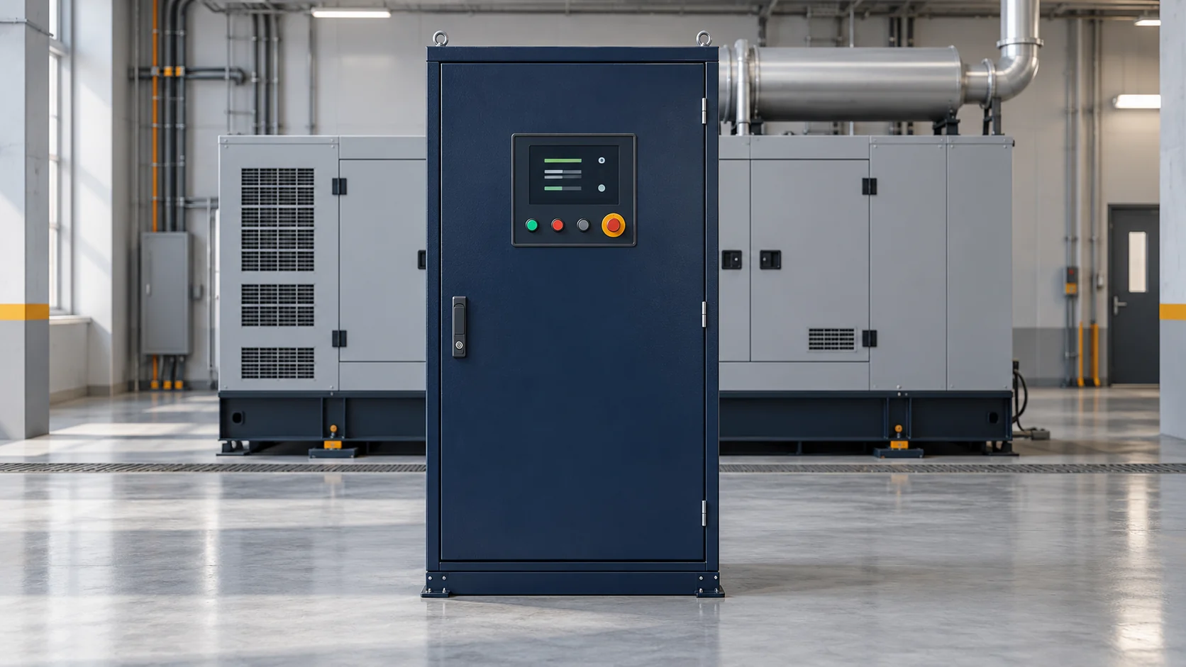
A generator panel can mean a controller, a cabinet or a wider assembly. Ask the supplier what each offer includes. Compare the parts listed in each offer. The generator controller reads supported signals and provides a user interface for staff.
Review generator configurations using the actual model data and required supply role.
Some generator panels combine control parts with switching or other power hardware. Others contain a controller panel that mainly displays data and sends control signals. Ask for the actual parts list and drawings to understand the proposed arrangement. Review each generator control panel against the actual model and project needs.
When comparing generator manufacturers, give each firm the same project brief. State the supply role and the readings staff need. Ask what the panel includes in the price. Check who will review the design and record its approved settings.
Two generator sets may need different sensors or control options. Ask which parts need a separate order. Keep each answer with the model name and document version. This creates a clear basis for comparing offers.
It does not replace the review of the actual site design.
Check the Readings
Check which engine readings the generator set and its sensors can show. These may include speed, battery voltage, temperature and oil pressure, depending on the equipment. A missing reading may reflect the sensors or setup.
A missing reading does not by itself confirm a fault. Use the maker’s current documents to check each value and unit. Follow their approved test conditions.
The DSE6120 MKIII page gives one example of engine and electrical monitoring. This model supports specified three-phase generator and mains sensing, plus current and power monitoring. Its engine sensing options depend on whether the engine uses CAN or other supported signals. Check these features against the model, sensors and setup you plan to use.
Read and Record Alarms
Follow the manual’s response for each warning or shutdown message. A warning does not prove that staff can safely continue running the set. Protection functions aim to help prevent damage, but they depend on proper design and settings. Use the manufacturer control-module example to review its stated functions and event logs.
Record the displayed alarm message, time, readings and relevant site conditions for review. Keep the fault history available to qualified staff along with the current manual. Follow the site’s approved response plan and seek help if the cause is unclear. Do not bypass protection or keep resetting alarms to force operation; this guide gives no reset or repair procedure.
When Power Is Restored
Check whether the chosen controller includes automatic mains failure functions for the planned system. During a power outage, the approved design determines how the system detects lost supply and responds. Ask qualified staff to confirm the required checks before starting the generator. Check start signals, timing and transfer behavior against the actual model, hardware and site plan.
Confirm the planned return logic with the site team. Review the return sequence in the approved site plan. Check any engine run-on or cooling period. The power source arrangement may use utility supply, a set or other approved sources.
Qualified staff confirm each planned control function against the current manual and drawings.
Review the Power Hardware
A controller’s signals are distinct from the hardware that switches the actual power supply. Complete cabinets may include circuit breakers or other power parts alongside the controls. Generator power ratings and the switching hardware’s limits need separate review for the project. Qualified engineers review the actual load path, equipment ratings and protection design.
Confirm which staff may change settings, connect inputs or maintain the actual system. The setup must suit the engine, sensors and power hardware. It must also fit the site design.
Arrange operation and maintenance support for the actual equipment and agreed scope, with the current documents available. This guide does not provide wiring instructions, protection settings or permission to work inside live electrical equipment.
Check Mounting and Support
Check the actual cabinet and controller requirements before choosing the mounting location. Check the maker’s limits for site conditions and mounting. Review the access space required for service. Some designs may allow a separate location, while others use a specified set-mounted arrangement.
Confirm the actual mounting plan and location with qualified staff.
Provide planners with the expected site conditions, access needs and proposed cable routes. They check the enclosure protection, connections and sensor layout against the actual design. Keep space for the approved service tasks and check the available documents at handover. Keep the model details, agreed functions, accepted settings and service contacts for later review.
Build a simple handover record from the approved site documents. The handover record should identify the controller, screen and supplied power parts. Identify each circuit breaker shown in the accepted design. Ask how the approved system may start the generator.
Note where staff can find the current manual and fault history. Record who may review settings and provide service support. Ask the site team to explain any limits to their staff. Keep those limits with the record.
The record should reflect the installed system, rather than a generic product name.